Application
- Maintaining of the equipment operation when voltage depression occurs;
- Safely shutdown of machineries;
- Maintaining "a bridge" when switching between the power supplies;
- Providing high discharging current in the equipment;
- Rapid electrical energy accumulation and further providing to the grid;
- Providing temporary electricity power for equipment while operating in autonomous mode;
- As an energy storage device in difficult remote equipment;
- As an power supply in single-use system;
- To improve the operational reliability of the equipment;
- Are used together with chemical and other current sources to extend the service life;
Main parameters
| Name | Value |
|---|---|
| Rated voltage, V | 2.7 |
| Rated capacitance, F | 1; 3; 5; 10; 15; 25; 50; 100; 200 |
| Capacitance tolerance, % | +50…-20; ±20 |
| Maximum operating temperature Tenv, °C | 65 |
| Minimal operating temperature Tenv, °C | -60 |
| Maximum-permissible overvoltage, V | 2.85 |
Dimensional drawing of capacitor
Figure 1

Figure 2
(also see fig. 1)
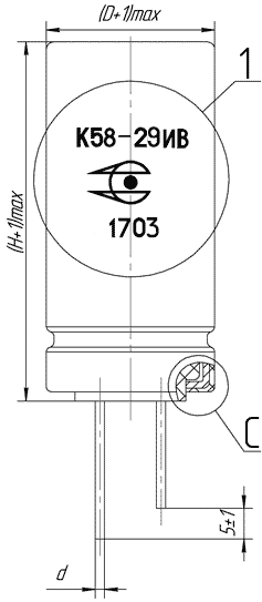
View B
(lid version 1)
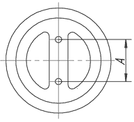
View B
(lid version 2)
Figure 3
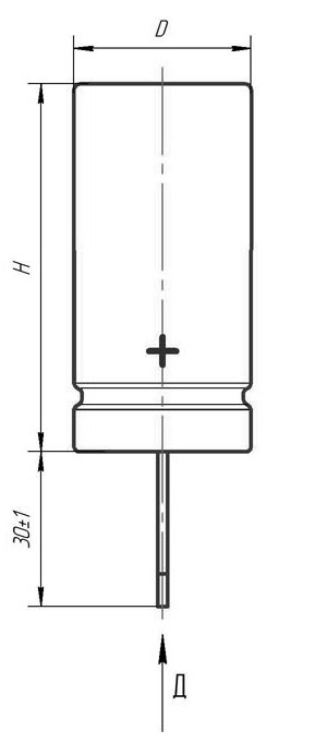
Figure 4
(also see fig. 2)
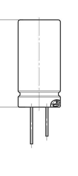
Д
(lid version 3)

Figure 5
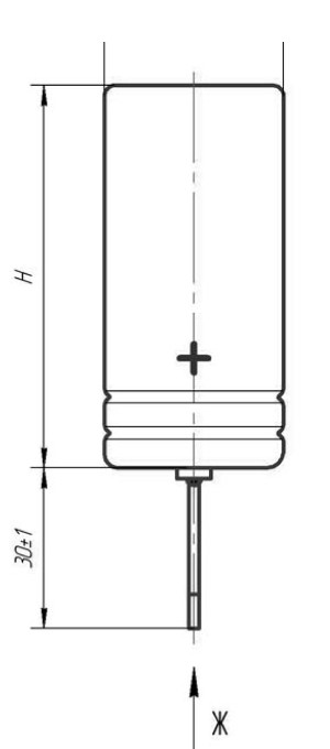
Figure 6
(also see fig. 1)
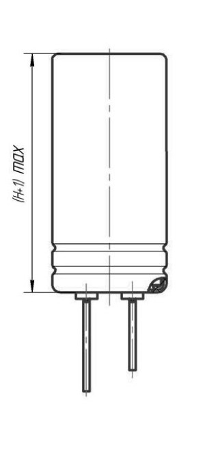
Ж
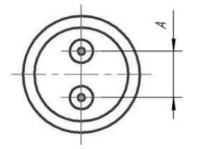
Capacitors overall dimensions and mass
| UR, V | CR, F | Size DxH, mm | d, mm | A, mm | Mass, g | Lid version | Figure |
|---|---|---|---|---|---|---|---|
| 2.7 | 1 | 6.3x14 | 0.6 | 2.3 | 2.5 | 2 | 1, 2, 3, 4 |
| 2.7 | 1 | 8x13 | 0.6 | 3.5 | 2.5 | 2, 3 | 1, 2, 3, 4 |
| 2.7 | 3 | 8x20 | 0.6 | 3.5 | 3.5 | 2, 3 | 1, 2, 3, 4 |
| 2.7 | 5 | 10x20 | 0.6 | 5 | 4.5 | 1 | 1, 2, 3, 4 |
| 2.7 | 10 | 10x30 | 0.6 | 5 | 6.5 | 1 | 1, 2, 3, 4 |
| 2.7 | 15 | 12.5x25 | 0.6 | 5 | 10.5 | 1 | 1, 2, 3, 4 |
| 2.7 | 25 | 16x25 | 0.8 | 7.5 | 15 | 1, 3 | 1, 2, 3, 4 |
| 2.7 | 50 | 18x40 | 0.8 | 7.5 | 25 | 1, 3 | 1, 2, 3, 4 |
| 2.7 | 100 | 20x40 | 0.8 | 10 | 45 | 1, 3 | 1, 2, 3, 4 |
| 2.7 | 200 | 25x60 | 1 | 12.5 | 90 | - | 5, 6 |
Case protection
| Climatic version | Lacquer coating | Jacketing with insulating tube | Design variant |
|---|---|---|---|
| Capacitors are intended for internal wiring with resistance to high humidity of 98% at the temperature 25°С | - | - | 1, 3, 5 |
| Capacitors are intended for internal wiring with resistance to high humidity of 98% at the temperature 25°С | - | + | 2, 4, 6 |
| Capacitors are intended for internal wiring with resistance to high humidity of 98% at the temperature 35°С | + | - | 2, 4, 6 |
| Capacitors are intended for internal wiring with resistance to high humidity of 98% at the temperature 35°С | + | + | 2, 4, 6 |
Capacitor electric parameters value
| UR, V | CR, F | Size DxH, mm | ILEAK, µA T=25°C, 72h | ESRDC, MOhm T=25°C | Maximum charging and discharging current, A (discharge within 1sec. from UR to ½UR) | Stored energy, Wh | Specific stored energy, Wh/kg | Specific output, W/kg |
|---|---|---|---|---|---|---|---|---|
| 2.7 | 1 | 6.3x14 | 15 | 400 | 0.5 | 0.001 | 0.41 | 874.8 |
| 2.7 | 1 | 8x13 | 15 | 400 | 0.5 | 0.001 | 0.41 | 874.8 |
| 2.7 | 3 | 8x20 | 15 | 110 | 1.5 | 0.003 | 0.87 | 2272.21 |
| 2.7 | 5 | 10x20 | 23 | 90 | 2.5 | 0.005 | 1.13 | 2160 |
| 2.7 | 10 | 10x30 | 38 | 70 | 5 | 0.010 | 1.56 | 1922.64 |
| 2.7 | 15 | 12.5x25 | 60 | 85 | 6.5 | 0.015 | 1.45 | 980.17 |
| 2.7 | 25 | 16x25 | 98 | 54 | 8.5 | 0.025 | 1.69 | 1080 |
| 2.7 | 50 | 18x40 | 240 | 32 | 10.1 | 0.051 | 2.03 | 1093.5 |
| 2.7 | 100 | 20x40 | 300 | 30 | 12.5 | 0.101 | 2.25 | 648 |
| 2.7 | 200 | 25x60 | 1 050 | 24 | 14 | 0.203 | 2.25 | 405 |
Capacitors reliability
| Reliability Operation modes | tλ, hours | tλ, cycles | λ, 1/hour, max |
|---|---|---|---|
| Maximum-permissible mode (UR, Tenv=65°С) | 1 500 | 5x |
|
| Maximum-permissible mode (charge to UR, discharge to ½UR, Tenv=65°С) | 30 000 | 3x |
|
| Typical operating mode (UR, Tenv=25°С) | 30 000 | 3x |
|
| Typical operating mode (charge to UR, discharge to ½UR, Tenv=25°С) | 500 000 | 3x |
Gamma-rated time of capacitor storageability Tcy at y=95%, 25 years

