Tantalum solid electrolyte chip capacitors produced by JSC Elecond are developed and manufactured in accordance with the requirements of the existing scientific and technical documentation. This is confirmed by tests to determine compliance with the existing scientific and technical documentation. These recommendations are based on the requirements of Technical Specifications, the most successful experiences worldwide and reference data and it allows selecting the operating mode of the capacitor according to the factors affecting the failure rate.
Main external factors affecting the failure rate:
- Temperature
- Voltage
1.
Temperature
Temperature at which operates a capacitor can reduce operational failure rate of chip capacitors by several times. The temperature dependence of failure rate of capacitors is shown in Table 1.
Table 1
| T, °C | 20 | 30 | 40 | 50 | 60 | 70 | 80 | 90 | 100 | 110 | 120 | 130 | 140 | 150 |
|---|---|---|---|---|---|---|---|---|---|---|---|---|---|---|
| KT | 0.91 | 1.1 | 1.3 | 1.6 | 1.8 | 2.2 | 2.5 | 2.8 | 3.2 | 3.7 | 4.1 | 4.6 | 5.1 | 5.6 |
It is also recommended to pay attention to the temperature shock in mounting the tantalum solid electrolyte chip capacitors that creates temporary mechanical stresses in capacitor dielectrics. It could cause dielectric damage and contributes to the volume growth of the amorphous oxide (dielectric), crystalline oxide that is an electrical conductor.
In the mounting of chip capacitors it is recommended:
- 1.1. Manual installation is to be performed by solder joints with the temperature of soldering tip from 235°C to 265°C, soldering time is max. 4 sec. for each contact point. At first soldering iron is to be attached to the contact point, to which the chip capacitor is soldered, and not to the contact point of the chip capacitor. Double soldering is not acceptable. (Special cases: tinning of leads, using of sealed-off chip capacitors).
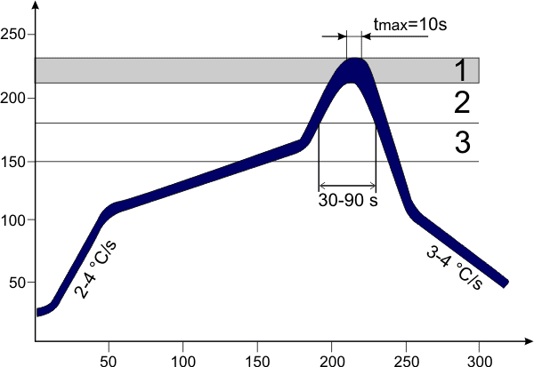
- 1.2. When soldering (melting solder paste) in conveyor furnaces, paraphrase ovens, infrared heating ovens temperature and exposure time must not exceed values provided in soldering profile in fig. 1.
Figure 1
Soldering profile in conveyor furnaces
T, °C
t, sec
Reference designation:
1 – soldering temperature 205-225°C
2 – melting temperature 179-183°C
3 – flux activation 150°C
- 1.3. When installing a PCB (a product) the temperature of capacitor shall not exceed operating temperature, except for soldering mode according to the p. 1.1 and 1.2 of these recommendations.
- 1.4. When designing, installing it is recommended not to locate capacitors near to fuel elements to prevent possible heating of capacitors.
2.
Voltage
The voltage supplied to the chip capacitor can significantly contribute to the failure rate. In the Table 2 are shown reference coefficient values of voltage applied that is used for calculation of the failure rate of chip capacitors.
Table 2
| Uраб/Uном | 0.1 | 0.2 | 0.3 | 0.4 | 0.5 | 0.6 | 0.7 | 0.8 | 0.9 | 1 |
|---|---|---|---|---|---|---|---|---|---|---|
| Kv | 1 | 1 | 1 | 1 | 1 | 2 | 15 | 130 | 990 | 5900 |
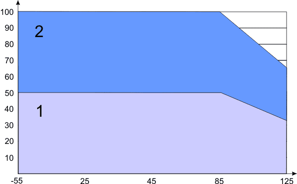
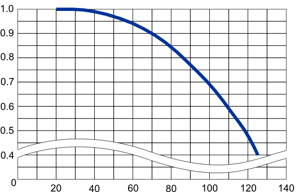
- 2.1. In accordance with the Table 2 permissible voltage (applied to the capacitor) versus temperature curve shall correspond to the Figure 2.
Figure 2
Rated (UR) and permissible (UP) voltage versus temperature curve
% of rated voltage
temperature ,°C
Reference designation:
1 – recommended voltage to be applied;
2 – short-term peak voltage
To ensure surge protection of dielectric all the solid tantalum capacitors need to have active resistance connected in series to the capacitor to limit current. Attention should be paid to the fact, that reducing impedance in circuit to which is connected a capacitor (capacitors), might increase the potential for its damage, especially with temperature rising. According to the reference data the change of ohmic coefficient used for failure rate calculation of capacitors is from KR= 0.07 at 3.0 Ohm/V to KR= 0.07 at 0.1 Ohm/V of the electrical circuit resistance connected in series to the capacitor.
If the capacitor is used with a limiting resistor of 3 ohm per 1 V of operating voltage, recommended permissible voltage Ut corresponds to the rated voltage UR, see blue area in Fig. 2. If using the limiting resistor is not possible, recommended permissible voltage Ut of capacitor, providing minimum failure rate of chip-capacitors, should not exceed 0.5UR, see blue area in Fig. 2. Short-time peak voltage to UR is allowed during 1*10-6-3 sec.
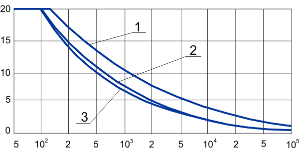
- 2.2. Recommended permissible voltage, providing minimum failure rate of chip-capacitors, includes pulsed/variable harmonic component, value of which should not exceed 20%. While supplying pulsed/variable harmonic component must be considered frequency and temperature dependences. Type of the recommended permissible pulsed/variable component dependence in the range of 5Hz to 100kHz is shown in Fig. 3.
Figure 3
Recommended permissible variable harmonic component range of pulsed voltage UF depending on working stress UT, providing minimum failure rate of chip-capacitors.
Uf/Ut, %
f, Hz
For capacitors with UR:
1 – 2.5 … 10 V
2 – 16 … 32 V
3 – 40 … 50 V
Reduction of recommended permissible AC voltage (Uf)/ permissible ripple current (Ip) and temperature dependence are shown in Fig. 4.
Figure 4
Permissible ripple current (Ip) and permissible AC voltage UF to temperature T diagram
Uf, Ip
Uf, Ip (20°C)
Uf, Ip (20°C)
T, °C
- 2.3. Supplying reverse voltage to the chip capacitor is prohibited, including measurement of capacitor parameters using LCR meter. The positive terminal is marked with color strip.
Parallel / series connection
When using parallel / series connection of capacitors it may happen that the electric load is distributed uneven between capacitors due to the presence of variation of electrical parameters of capacitors. It leads to increasing failure rate of overloaded elements. You need to choose capacitors by electrical resistance (if possible at operating frequency).
Incoming inspection
At incoming inspection of electrical parameters (C (capacitance), D (dielectric dissipation factor), R (active resistance), Z (impedance) it is recommended to use LCR meters, that ensure supplying to the capacitors direct bias voltage of 2V. Measuring signal frequency must comply with the technical specifications for capacitors and requirements of industrial engineering documentation. To measure leakage current may be used source measurement unit or special device type leakage current meter “Chroma 11200”. While measuring use special contact devices that ensure measurement accuracy required. After measurement discharge the capacitors.