Methodology for testing the electrical parameters of low-voltage foil
- 1) Forming etched foil samples
- 2) Measuring forming stress
- 3) Measuring capacity
- 4) Control of oxide layer stability
1. FORMING ETCHED FOIL SAMPLES
-
DC power supply
- ripple ≤ 1%;
- voltage stability ± 3% - DC Voltmeter - Accuracy ± 0.5%
- DC Ammeter - Accuracy ±1.0%
- Stainless steel bath, temperature control
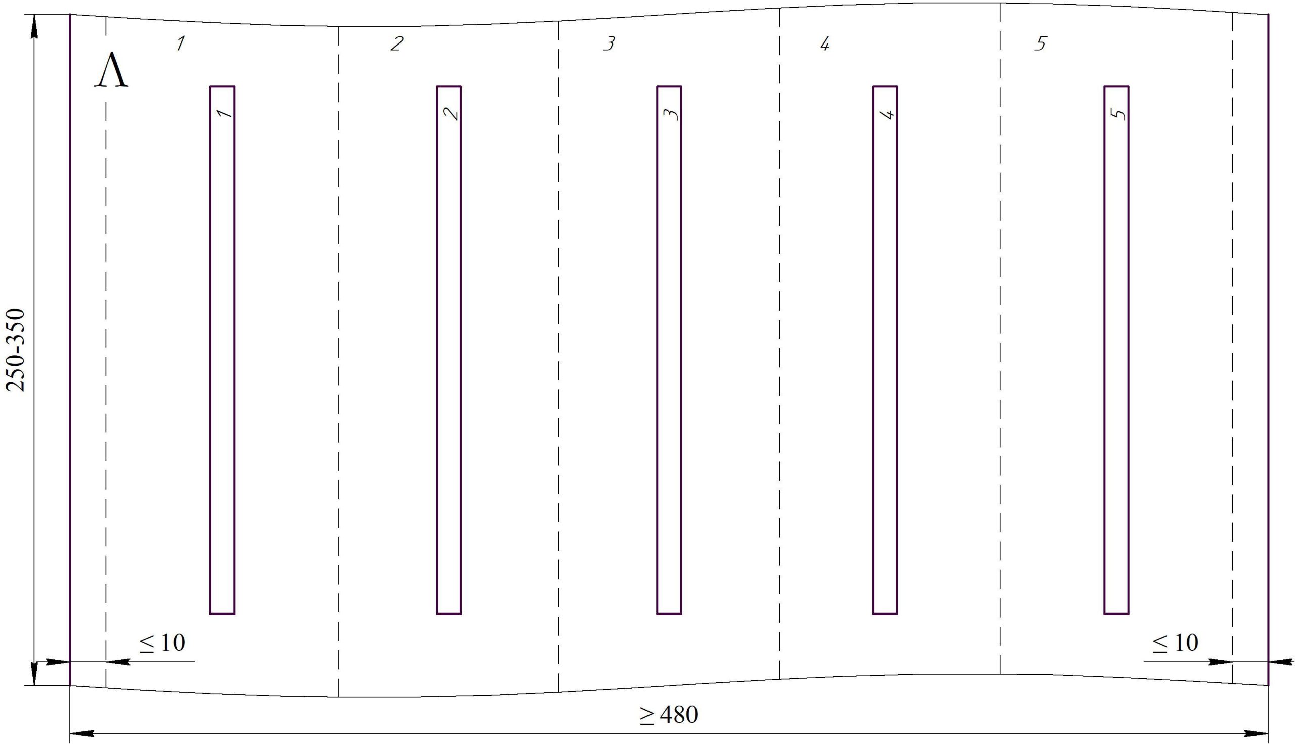
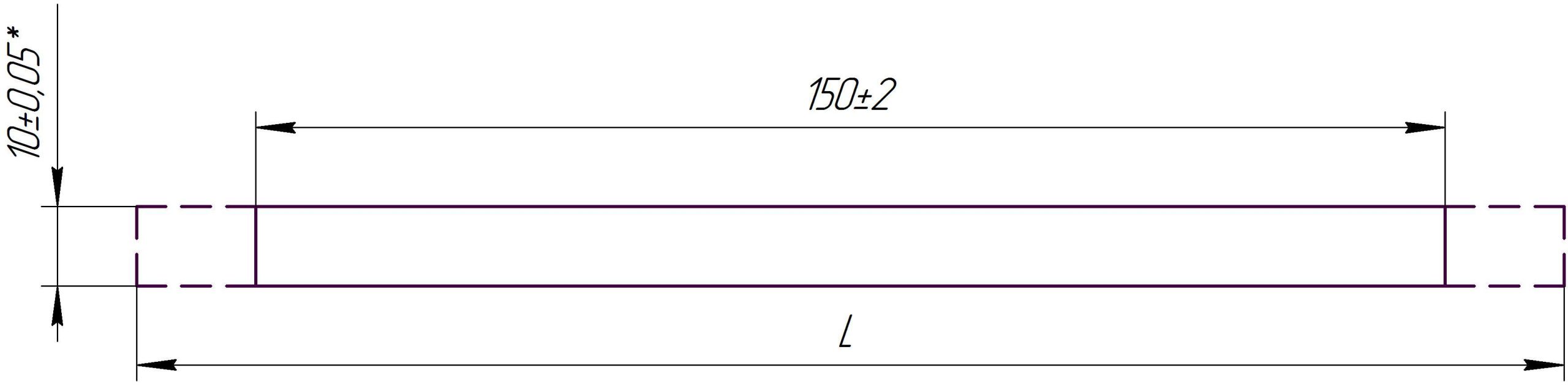
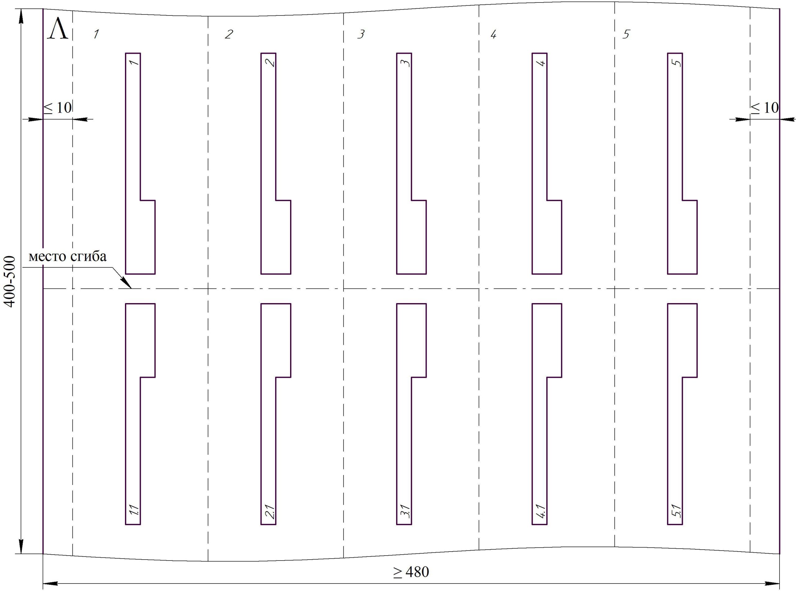
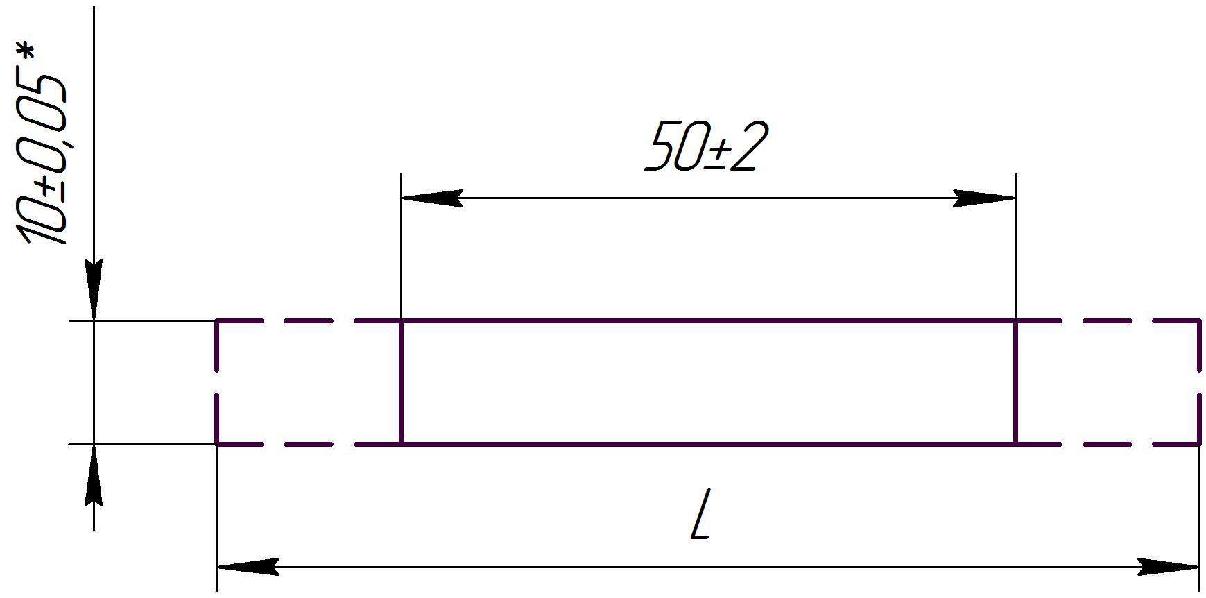
* The size is determined by the tool.
L is the specimen output length, determined by the equipment used.
The specimen edges must be trimmed without breaks or burrs.
- Ammonium adipate - 150 g
- Deionized water (≤ 0.1 μS/cm) - 1000 ml
- Electrolyte resistance at + 70 °C: 5.0 - 8.5 Ohm‧cm
- pH, at + 50 °C - 5.2 - 7.2
- Forming current - 0.3 A/sample
- Electrolyte temperature: 70±2°C
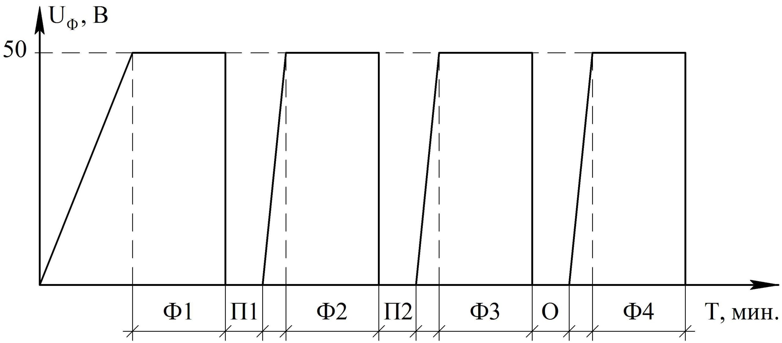
Forming cycle (F1; F2; F3; F4) – 6 minutes;
Pause between molding cycles (P1; P2) – 1 minute;
Annealing from plus 510 to plus 530 °C (O) – 1 minute.
2. Measuring forming stress
-
DC power supply
- ripple ≤ 1%;
- voltage stability ± 3% - DC Voltmeter - Accuracy ± 0.5%
- DC Ammeter - Accuracy ±1.0%
- Stainless steel bath, temperature control
- Ammonium adipate - 150 g
- Deionized water (≤ 0.1 μS/cm) - 1000 ml
- Electrolyte resistance at + 70 °C: 5.0 - 8.5 Ohm‧cm
- pH, at + 50 °C - 5.2 - 7.2
- Test current - 2.0 ± 0.2 mA/sample
- Electrolyte temperature: 70 ± 2 °C
3. Measuring capacity
- Faradmeter - accuracy ± 1%
- Measuring frequency: 100 Hz ± 5% (50 Hz allowed)
- Cell made of inert material
- The counter electrode is etched thermally oxidized foil with a capacitance of ≥ 40,000 μF/dm²
- Ammonium adipate - 150 g
- Deionized water (≤ 0.1 μS/cm) - 1000 ml
- Electrolyte resistance at + 70 °C: 5.0 - 8.5 Ohm‧cm
- Electrolyte temperature: 20 - 25 °C
- 1) Place the molded foil sample in a measuring cell with electrolyte so that only the working part of the sample (without the terminal) is immersed in the electrolyte.
- 2) Keep the sample for 1 minute, then measure the capacity.
- 3) Multiply the capacitance value obtained from the device by 10 to obtain the specific capacitance value in μF/dm².
4. Control of oxide layer stability
- Time: 60 ± 1 minute
- Temperature: ≥ 95 °C
- Number of samples: ≤ 6
- Replace deionized water: after each hydration process.
- Ammonium adipate - 150 g
- Deionized water (≤ 0.1 μS/cm) - 1000 ml
- Electrolyte resistance at + 70 ºС — 5.0 - 8.5 Ohm‧cm
- Test current - 2.0 ± 0.2 mA/sample
- Electrolyte temperature: 85 ± 2°C
- 1) Place the test specimen into the electrolyte so that the upper edge of the protruding area (to be measured) is level with the surface.
- 2) Measure the time to reach 0.9UF.
METHOD FOR TESTING ELECTRICAL PARAMETERS OF HIGH-VOLTAGE FOIL
- 1) Forming etched foil samples
- 2) Measuring forming stress
- 3) Measuring capacity
- 4) Control of oxide layer stability
1. FORMING ETCHED FOIL SAMPLES
-
DC power supply
- ripple ≤ 1%;
- voltage stability ± 3% - DC Voltmeter - Accuracy ± 0.5%
- DC Ammeter - Accuracy ±1.0%
- Stainless steel bath, temperature control
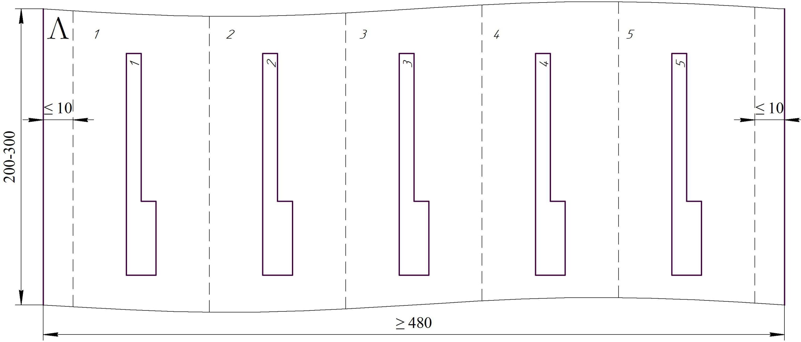
* The size is determined by the tool.
L is the specimen output length, determined by the equipment used.
The specimen edges must be trimmed without breaks or burrs.
1.1. FORMING SAMPLES OF ETCHED FOIL FOR SUBSEQUENT FORMING IN ELECTROLYTE No. 4
- Citric acid - 2 g
- Deionized water (≤ 0.1 μS/cm) - 1000 ml
- Electrolyte resistance at + 30ºС — 1000 ± 50 Ohm‧cm
- Forming current - 0.5 A/sample
- Electrolyte temperature: 90±2°C
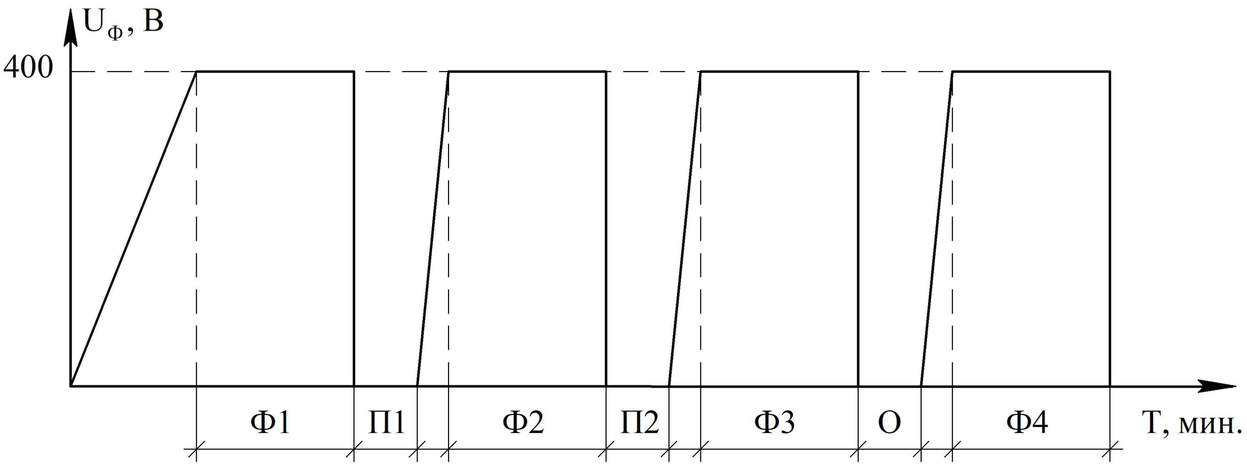
Forming cycle (F1; F2; F3; F4) — 10 minutes;
Pause between forming cycles (P1; P2) — 2 minutes;
Annealing at 250°C (O) — 2 minutes.
1.2. FORMING SAMPLES OF ETCHED FOIL FOR SUBSEQUENT FORMING IN ELECTROLYTE No. 1
- Time: 15 ± 1 minute
- Temperature: ≥ 95 °C
- Number of samples: ≤ 6
- Replace deionized water: after each hydration process
- Boric acid - 100 g
- Deionized water (≤ 0.1 μS/cm) - 900 ml
- Boric acid - 100 g
- Ammonium pentaborate, tetrahydrate - 0.7 g
- Deionized water (≤ 0.1 μS/cm) - 900 ml
- Forming current - 0.5 A/sample
- Electrolyte temperature: 90±2°C
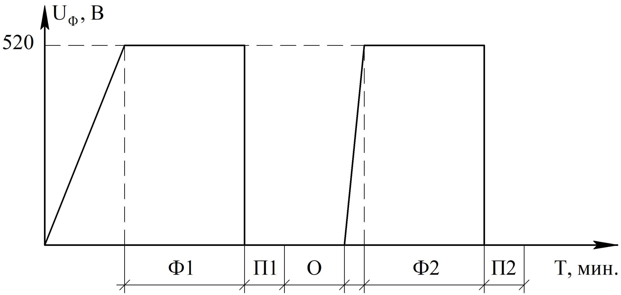
Forming cycle F1 – 10 minutes;
Rinse 1 (P1) – 1 minute;
Annealing from plus 510 to plus 530 °C (O) – 2 minutes;
Forming cycle (F2) – until the forming current drops to 0.03 A;
Rinse 2 (P2) – 1 minute.
2. Measuring forming stress
-
DC power supply
- ripple ≤ 1%;
- voltage stability ± 3% - DC Voltmeter - Accuracy ± 0.5%
- DC Ammeter - Accuracy ±1.0%
- Stainless steel bath, temperature control
- Boric acid - 70 g
- Deionized water (≤ 0.1 μS/cm) - 1000 ml
- Electrolyte conductivity at + 70 °C: 7,500 ± 300 Ohm‧cm
- Boric acid - 40 g
- Deionized water (≤ 0.1 μS/cm) - 1000 ml
- Electrolyte conductivity at + 70 °C: 19,000 ± 1,000 Ohm‧cm
- Boric acid - 30 g
- Deionized water (≤ 0.1 μS/cm) - 1000 ml
- Electrolyte conductivity at + 70 °C: 28,900 ± 1,500 Ohm‧cm
- Boric acid - 20 g
- Deionized water (≤ 0.1 μS/cm) - 1000 ml
- Electrolyte conductivity at + 70 °C: 46,500 ± 2,500 Ohm‧cm
- Test current - 4.0 ± 0.2 mA/sample
- Electrolyte temperature: 90 ± 2 °C
3. Measuring capacity
- Faradmeter - accuracy ± 1%
- Measuring frequency: 100 Hz ± 5% (50 Hz allowed)
- Cell made of inert material
- The counter electrode is etched thermally oxidized foil with a capacitance of ≥ 40,000 μF/dm²
- Ammonium adipate - 100 g
- Deionized water (≤ 0.1 μS/cm) - 1000 ml
- Electrolyte resistance at + 20 ºС — 16–20 Ohm‧cm
- Electrolyte temperature: 20 - 25 °C
- 1) Place the molded foil sample in a measuring cell with electrolyte so that only the working part of the sample (without the terminal) is immersed in the electrolyte.
- 2) Keep the sample for 1 minute, then measure the capacity.
- 3) Multiply the capacitance value obtained from the device by 10 to obtain the specific capacitance value in μF/dm2.
4. Control of oxide layer stability
- Time: 60 ± 1 minute
- Temperature: ≥ 95 °C
- Number of samples: ≤ 6
- Replace deionized water: after each hydration process
- Boric acid - 70 g
- Deionized water (≤ 0.1 μS/cm) - 1000 ml
- Electrolyte conductivity at + 70 °C: 7,500 ± 300 Ohm‧cm
- Boric acid - 40 g
- Deionized water (≤ 0.1 μS/cm) - 1000 ml
- Electrolyte conductivity at + 70 °C: 19,000 ± 1,000 Ohm‧cm
- Boric acid - 30 g
- Deionized water (≤ 0.1 μS/cm) - 1000 ml
- Electrolyte conductivity at + 70 °C: 28,900 ± 1,500 Ohm‧cm
- Boric acid - 20 g
- Deionized water (≤ 0.1 μS/cm) - 1000 ml
- Electrolyte conductivity at + 70 °C: 46,500 ± 2,500 Ohm‧cm
- Test current - 4.0 ± 0.2 mA/sample
- Electrolyte temperature: 90 ± 2 °C
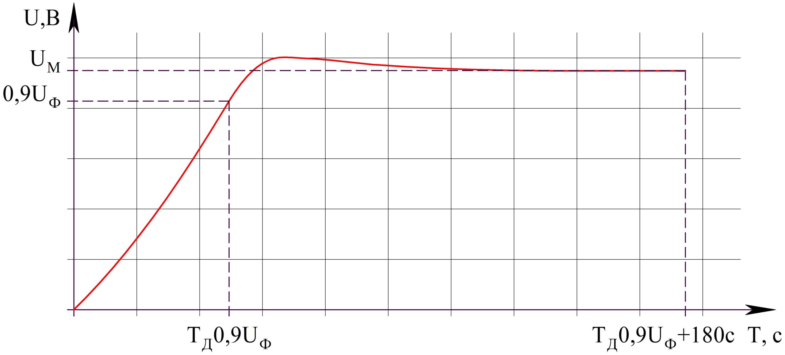
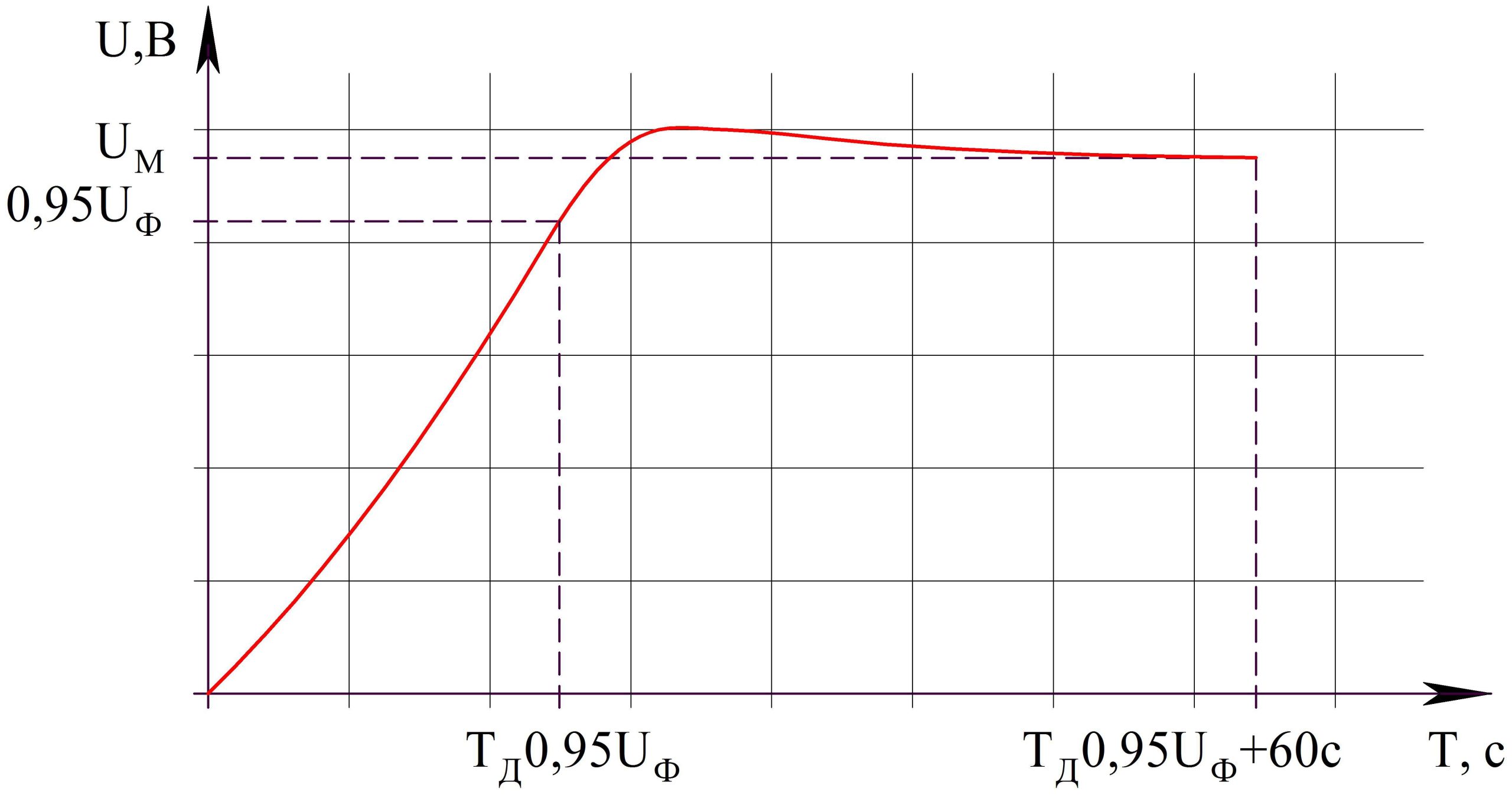
- 1) Place the test specimen into the electrolyte so that the upper edge of the protruding area (to be measured) is level with the surface.
- 2) Measure the time to reach 0.95 UФ and the maximum voltage gained (UМ) 60 seconds after TД 0.95UФ.
METHOD FOR TESTING THE ELECTRICAL PARAMETERS OF CATHODE FOIL
- 1) Measuring capacity
- 2) Quality control of stabilization
1. MEASURING CAPACITY
- Faradmeter - accuracy ± 1%
- Measuring frequency: 100 Hz ± 5% (50 Hz allowed)
- Cell made of inert material
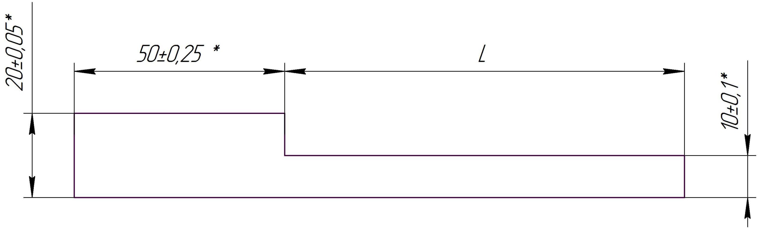
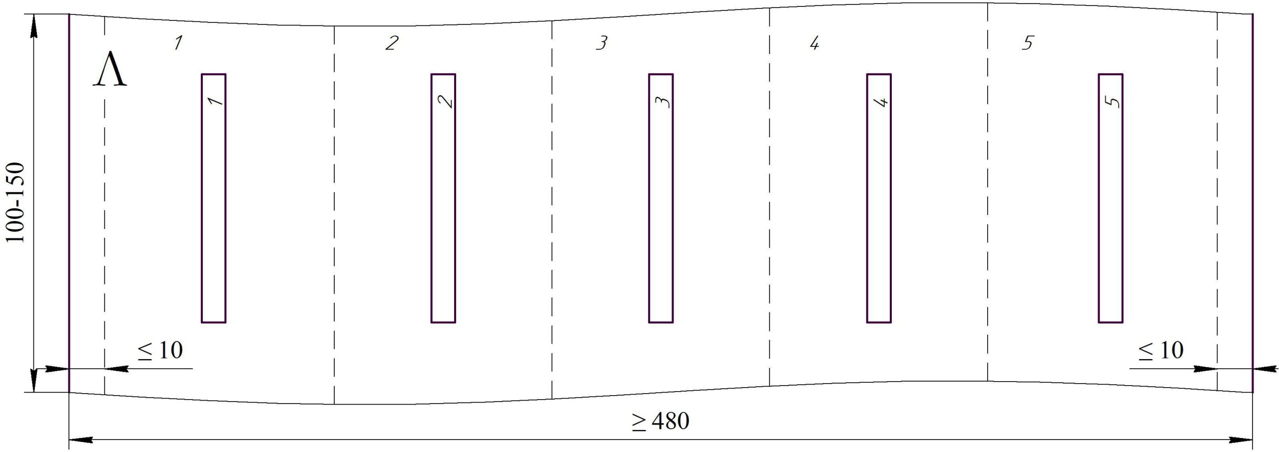
* The size is determined by the tool.
L is the specimen output length, determined by the equipment used.
The specimen edges must be trimmed without breaks or burrs.
- Ammonium adipate - 150 g
- Deionized water (≤ 0.1 μS/cm) - 1000 ml
- Electrolyte resistance at + 70°C: 5.0 … 8.5 Ohm×cm
- Electrolyte temperature: 20 - 25 °C
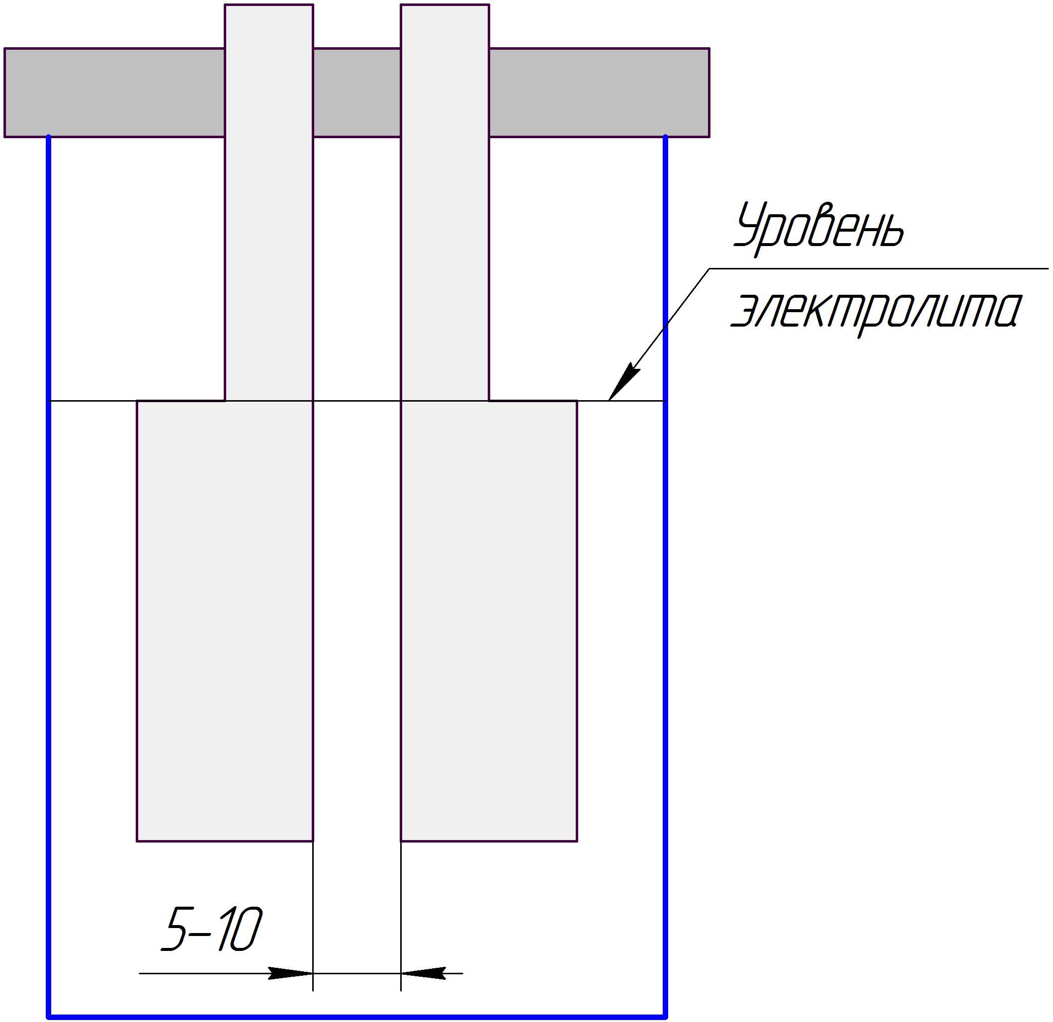
- 1) Place two controlled samples (located one above the other, according to the sampling scheme) in a cell, as shown in the figure.
- 2) Keep the sample for 1 minute, then measure with a container.
- 3) Multiply the capacitance value obtained from the device by 20 to obtain the specific capacitance value in μF/dm2.
2. STABILIZATION QUALITY CONTROL
- Time: 30 ± 1 minute
- Temperature: ≥ 95°C
- Number of samples: ≤ 6
- Replace deionized water: after each hydration process
- Ammonium adipate - 150 g
- Deionized water (≤ 0.1 μS/cm) - 1000 ml
- Electrolyte resistance at + 70 °C: 5.0 - 8.5 Ohm‧cm
- Electrolyte temperature is 20 - 25 °C.
- Measure the specific capacity according to point 1
METHOD FOR DETERMINING RESIDUAL CHLORINE ON FOIL
- Heating plate
- Bath for cooling
- Glasses, flasks, burettes, pipettes as needed
- Nitric acid 65%, chemically pure
- Silver nitrate, analytical grade
- Deionized water (≤ 0.1 μS/cm)
- Estimated area 0.1 m² (taking into account the surface of both sides), cut into strips 20–25 mm wide.
- 1) Roll the strips into loose rolls, place them in a flask and pour 100 ml of 5% nitric acid solution into it.
- 2) Heat the flask in a water bath to a temperature of 40-45 °C, hold for 10 minutes, stirring the rolls with a glass rod.
- 3) Remove the rolls from the solution, allowing the solution to drain, and cool the solution.
- 4) Filter the solution until it is completely clear.
- 5) Add 10 drops of 5% silver nitrate solution to the test solution and the standard scale solutions.
- 6) After 10 minutes, compare the opalescence of the test solution with the standard scale solutions.
BENDING TEST METHOD
- Setting the foil fold count
* The size is determined by the tool.
L is the specimen output length, determined by the equipment used.
The specimen edges must be trimmed without breaks or burrs.
| Тип фольги | Радиус изгиба, мм |
|---|---|
| Травленая анодная высоковольтная | 0,5 ± 0,05 |
| Формованная анодная низковольтная | 0,5 ± 0,05 |
| Формованная анодная высоковольтная | 0,5 ± 0,05 |
| 3,5 ± 0,35 | |
| Катодная травленая | 1,0 ± 0,10 |
| Катодная отожжённая |
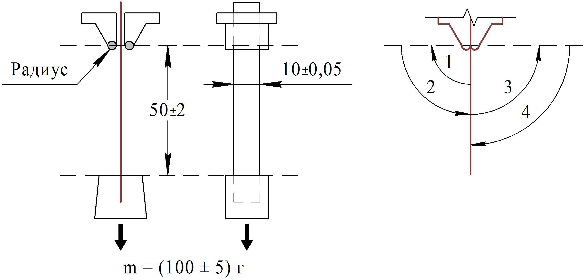
– One bend is defined as a 90° turn
– The test is carried out until the foil breaks
TEAR RESISTANCE TEST METHOD
- Tensile testing machine, measurement range: forces - from 0 to 500 N, measurement error no more than 1%, moving speed of the movable clamp 50 - 60 mm/min.