Leading manufacturer of capacitors in Russia
Marketing department
Product сatalog > Capacitors > Aluminum electrolytic > K50-106
Product сatalog > Capacitors > Tantalum wet-slug > K50-106
Product сatalog > Capacitors > Tantalum solid-electrolyte > K50-106
Product сatalog > Capacitors > Niobium solid-electrolyte > K50-106
Find out about delivery times, product costs or just ask a question
1
1.1
2
3
4
5
6
7
8
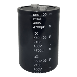
Capacitor K50-106
b
400V
3300µF
±20%
D=65mm
H=105.7mm
PET
EVAYA.673541.063 TU
K50-106
B
Y
338
M
D65
H105Z7
063
Code
The presence of a hairpin
A
Without end pin
With end pin
U
UR, V
400
450
478
688
CR, µF
3300
4700
6800
Admittance, %
±20
D76
Diameter, mm
65
76
H143Z2
Height, mm
105.7
143.2
Decryption
Isolated, packed in a box for manual assembly of equipment
TU designation
K50-15
K50-17
K50-27
K50-29
K50-37
K50-68
K50-77
K50-77 OTK
K50-80
K50-81
K50-83
K50-84
K50-85
K50-86
K50-87
K50-88
K50-89
K50-90
K50-91
K50-92 OTK
K50-92
K50-93
K50-95
K50-94
K50-96
K50-97
K50-98
K50-99
K50-100
K50-102
K50-103
K50-104
K50-105
K50-101
Capacitors
Supercapacitors
Supercapacitors modules
Aluminium foil
Leave your contact details and our specialist will contact you shortly