

Main parameters
| Name | Value |
|---|---|
| Rated voltage, V | 250…450 |
| Rated capacitance, µF | 100…680 |
| Temporary overvoltage within 10 sec., V | 1.15 UR (UR=250) 1.1 UR (UR>250) |
| Capacitance tolerance (25 °C, 50 Hz), % | +50…-20; ±20 |
| Maximum operating temperature Tenv, °C | +85 |
| Minimal operating temperature Tenv, °C | -40 |
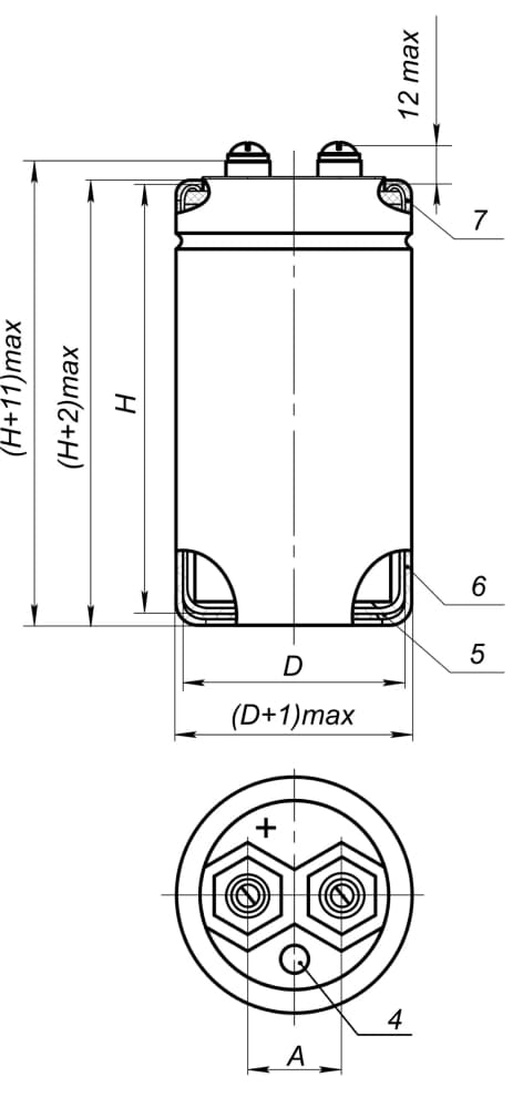
Capasitor physical configuration
All climate
(Isolated)
(Isolated)
Temperate/cold climate
version (Nonisolated)
version (Nonisolated)
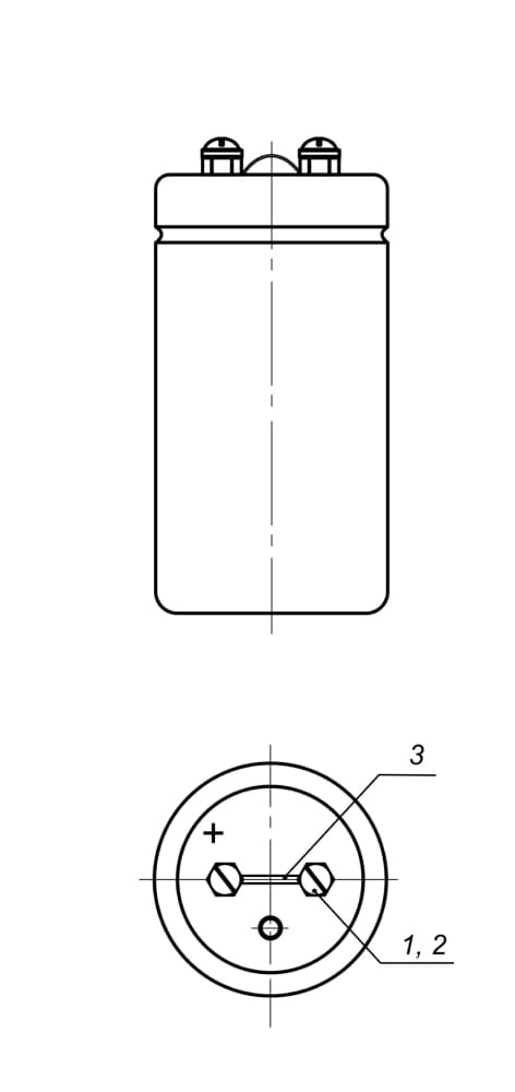
1 – Screw BM5-6g
2 – Washer 5.65
3 – Jumper for discharge
4 – Explosion proof valve
5 – Insulating gasket
6 – Enameling
7 – Insulating tube
2 – Washer 5.65
3 – Jumper for discharge
4 – Explosion proof valve
5 – Insulating gasket
6 – Enameling
7 – Insulating tube
| D, mm | A, mm |
|---|---|
| 35 | 12.5 |
| 50 | 22 |
Capacitors reliability
| Reliability Operation modes | Minimal nonfailure operating time, tλ, hours | Capacitor failure rate, λ, 1/hour, max |
|---|---|---|
| Maximum-permissible mode (UR, Tenv=85 °С) | 10 000 | 10-5 |
| Light mode (0.5UR, Tenv=60 °С) | 50 000 | 10-6 |
| Light mode (0.5UR, Tenv=50 °С) | 100 000 | 10-7 |
| Storageability Gamma-rated time of capacitor storageability Tcy at y=99.5%, years, min | 25 | |
Dimension sizes and capacitor electric parameters value when delivered
| UR, V | CR, µF | Size DxH, mm | tg δ, %, 25°C, 50 Hz, max | ILEAK, µA, 25°C, after 5 min., max | Mass, g, max | Z, Ohm, 25°C, 100kHz, max | IR, А, 85°C, 50 Hz, max |
|---|---|---|---|---|---|---|---|
| 250 | 680 | 35x60 | 25 | 1 379 | 150 | 0.95 | 0.7 |
| 50х45 | 120 | ||||||
| 350 | 150 | 35x40 | 608 | 85 | 2.30 | 1.2 | |
| 220 | 35x45 | 794 | 120 | 1.35 | 1.3 | ||
| 330 | 35x50 | 1 053 | 140 | 0.75 | 1.4 | ||
| 470 | 35x60 | 1 348 | 150 | 1.6 | |||
| 50x45 | |||||||
| 400 | 100 | 35x40 | 504 | 85 | 5.80 | 1.7 | |
| 150 | 35x45 | 667 | 120 | 3.10 | 1.8 | ||
| 220 | 35x50 | 871 | 140 | 1.80 | 1.9 | ||
| 330 | 35x60 | 1 156 | 150 | 1.55 | 2.2 | ||
| 50x45 | |||||||
| 470 | 35x80 | 1 480 | 160 | 0.90 | 2.8 | ||
| 50x50 | 185 | ||||||
| 450 | 100 | 35x45 | 546 | 120 | 6.55 | 1.3 | |
| 150 | 35x50 | 724 | 140 | 3.50 | 1.4 | ||
| 220 | 35x60 | 946 | 150 | 3.40 | 1.6 | ||
| 50x45 | |||||||
| 330 | 35х80 | 1 255 | 160 | 1.75 | 2.0 | ||
| 50х50 | 185 |
Ripple current effective value
versus temperature and frequency can be found from the formula IRO = IR x KT x KF, where
IR– allowable ripple current at 85 °C, 50 Hz (See Table “Capacitor electric parameters”)
versus temperature and frequency can be found from the formula IRO = IR x KT x KF, where
IR– allowable ripple current at 85 °C, 50 Hz (See Table “Capacitor electric parameters”)
KT - IR correction factor versus temperature
| Tenv, °C | 25 | 40 | 50 | 60 | 70 | 85 |
|---|---|---|---|---|---|---|
| KT | 1.43 | 1.37 | 1.31 | 1.25 | 1.17 | 1.0 |
KF - IR correction factor versus frequency
| F, Hz | 50 | 100 | 300 | 600 | 1 000 | 10 000 | ≥50 000 |
|---|---|---|---|---|---|---|---|
| KF | 1 | 1.25 | 1.5 | 1.63 | 1.69 | 1.88 | 2.0 |