

Main parameters
| Name | Value |
|---|---|
| Rated voltage, V | 16…160 |
| Rated capacitance, µF | 680…22 000 |
| Temporary overvoltage within 10 sec., V | 1.15 UR |
| Capacitance tolerance (25 °C, 50 Hz), % | +30…-10 |
| Maximum operating temperature Tenv, °C | +100 |
| Minimal operating temperature Tenv, °C | -60 |
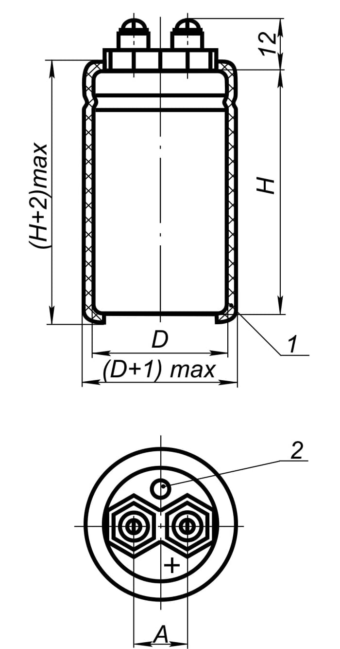
Temperate/cold climate version
All climate version
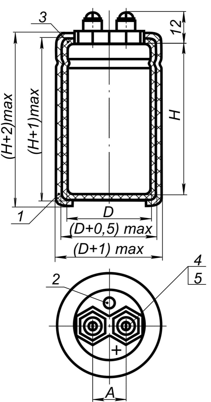
Spacing between terminals is 12.5±0.15 mm
1 – Insulating cover
2 – Explosion proof valve
3 – Paintwork
4 – Screw BM5-6g
5 – Washer 5.65
2 – Explosion proof valve
3 – Paintwork
4 – Screw BM5-6g
5 – Washer 5.65
Capacitors overall dimensions and mass
| UR, V | 16 | 25 | 40 | 63 | 100 | 160 |
|---|---|---|---|---|---|---|
| CR, µF | DxH, mm mass, g |
|||||
| 680 | 35x55 75 |
|||||
| 1 000 | 35x80 110 |
|||||
| 2 200 | 35x55 75 | 35x80 110 | ||||
| 3 300 | 35x80 110 | |||||
| 4 700 | 35x55 75 | 35x80 110 | ||||
| 6 800 | 35x55 75 | 35x80 110 | ||||
| 10 000 | 35x55 75 | 35x80 110 | 35x80 110 | |||
| 15 000 | 35x80 110 | |||||
| 22 000 | 35x80 110 | |||||
Capacitor electric parameters value when delivered
| CR, µF | UR, V | tg δ, %, 25 °C, 50 Hz, max | ILEAK, µA, 25°C, after 5 min., max | Z, Ohm, 25°C, 100kHz, max | ESR, Ohm, 25°C, 100kHz, max | IR, А, 85°C, 50 Hz, max |
|---|---|---|---|---|---|---|
| 16 | 10 000 | 25 | 1 320 | 0.03 | 0.038 | 9.6 |
| 15 000 | 1 617 | 0.025 | 0.026 | 12.8 | ||
| 22 000 | 1 958 | 0.018 | 0.021 | 13.6 | ||
| 25 | 6 800 | 1 360 | 0.027 | 0.032 | 10.4 | |
| 10 000 | 1 650 | 0.021 | 0.028 | 12 | ||
| 40 | 4 700 | 20 | 1 431 | 0.028 | 0.033 | 11.2 |
| 6 800 | 1 721 | 0.022 | 0.028 | 12.8 | ||
| 10 000 | 2 087 | 0.017 | 0.027 | 15.2 | ||
| 63 | 2 200 | 15 | 1 230 | 0.03 | 0.06 | 7.5 |
| 3 300 | 1 505 | 0.024 | 0.039 | 11.2 | ||
| 4 700 | 1 796 | 0.02 | 0.031 | 13.6 | ||
| 100 | 2 200 | 1 548 | 0.03 | 0.057 | 9.6 | |
| 160 | 680 | 10 | 1 089 | 0.048 | 0.092 | 1.9 |
| 1 000 | 1 320 | 0.052 | 0.084 | 2.2 |
Ripple current effective value
versus temperature and frequency can be found from the formula IRO = IR x KT x KF, where
IR– allowable ripple current at 85 °C, 50 Hz (See Table “Capacitor electric parameters”)
versus temperature and frequency can be found from the formula IRO = IR x KT x KF, where
IR– allowable ripple current at 85 °C, 50 Hz (See Table “Capacitor electric parameters”)
KT - IR correction factor versus temperature
| Tenv, °C | 40 | 50 | 60 | 70 | 85 | 100 |
|---|---|---|---|---|---|---|
| KT | 1.7 | 1.65 | 1.6 | 1.3 | 1 | 0.5 |
KF - IR correction factor versus frequency
| F, Hz | 50 | 100 | 200 | 300 | 400 | 500 | 1 000 | ≥2 000 |
|---|---|---|---|---|---|---|---|---|
| KF | 1 | 1.25 | 1.4 | 1.48 | 1.51 | 1.54 | 1.58 | 1.6 |
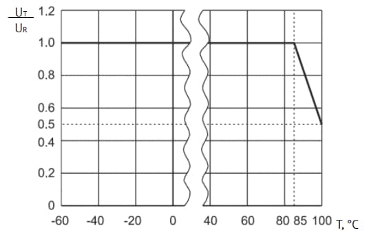
Voltage versus temperature
Capacitors reliability
| Reliability Operation modes | Minimal nonfailure operating time, tλ, hours | Capacitor failure rate, λ, 1/hour, max |
|---|---|---|
| Maximum-permissible mode (UR, Tenv=85 °С) | 10 000 | 10-6 |
| Maximum-permissible mode (0.5UR, Tenv=100 °С) | 10 000 | 10-6 |
| Light mode (0.6UR, Tenv=40 °С) | 100 000 | 10-7 |
| Storageability Gamma-rated time of capacitor storageability Tcy at y=95%, years, min | 25 | |